
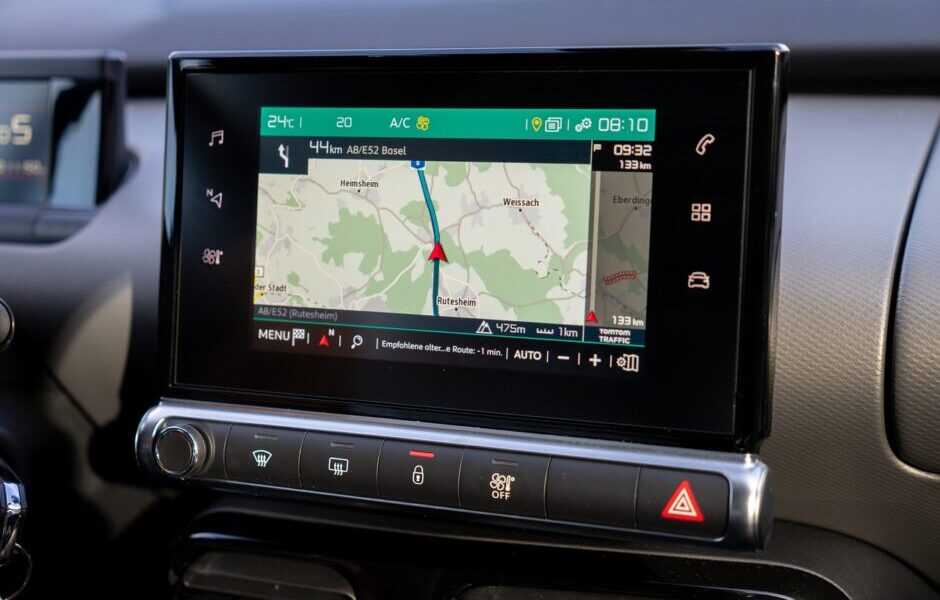
A navigation device is a common gadget nowadays. Almost every one of us has used it. Even in our smartphones, we have a default map navigation app that guides us at every turn in the street and helps us in locating our destinations. The map navigation app is no longer regarded as a required app; it has really become an essential app. Whether it is a navigation device or app, at the backend there is a navigation system. So, have you ever wondered how the map navigation system works?
Since I have worked in the mapping domain at HERE Technologies, I understand the technical details of a map navigation system, and so here I will try to explain in simple words how it works.
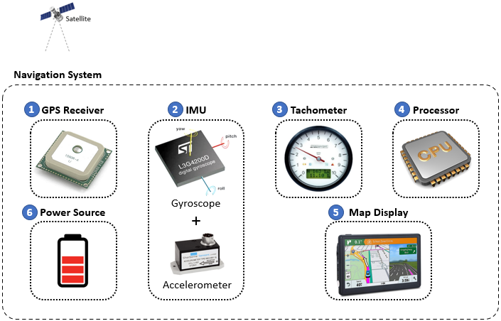
A simple navigation system has at least the following six main integrated components that are essential for its functioning to show the user the location and movement of the system or unit.
- A GPS Receiver to receive the respective geo-positioning satellite system’s signals
- An Inertial Measurement Unit (IMU) with a calibrated combination of a gyroscope and an accelerometer for measuring the gravitational acceleration of the unit
- A Tachometer, to calculate the speed of the unit based on its Lat./Long. coordinates changes
- A Processor to process and calculate all the values, like current location, change in position, acceleration, speed, etc., before showing the final output in the display unit.
- A Display unit with map data to show the ground positions and movements
- A Power source to continuously provide power to the receiver and other components
An illustration of the integrated components of a navigation system is shown in the image below. I will describe the functionalities of the individual components further below. But let’s first see how the geolocation or geo-positioning is done with navigation satellites.
The most important part of any navigation system is the process of geolocating the object on the surface of the earth that has the satellite signal receiver. The satellite can be part of any navigation satellite system, like the United States’ GPS, Russia’s GLONASS, the European Union’s Galileo, Japan’s MSAS, or India’s GAGAN or NAVIC, etc., depending on the make of the signal receiver device. For this blog, I will refer to the most common navigation satellite system – the GPS.
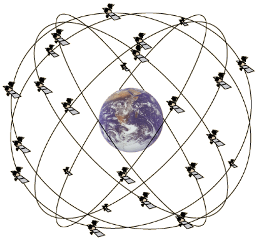
GPS or Global Positioning System, is a worldwide radio-navigation system formed from a set of constellations of 24 satellites (figure below) and their ground stations. The Global Positioning System is mainly funded and controlled by the U.S. Department of Defence (DOD). The system was initially designed for the operation of the U.S. military. But today, there are also many civil users of GPS across the world. The civil users are allowed to use the Standard Positioning Service without any kind of charge or restrictions, and hence we see GPS is mostly popular worldwide, and GPS Navigation System became the synonym for Satellite Navigation System.
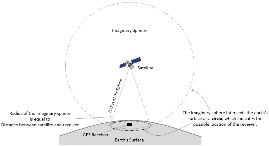
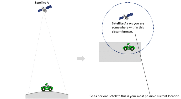
A Satellite Navigation System may be placed in a vehicle, on a cell phone, or on special GPS devices, which can either be a fixed or portable unit. To geolocate an object (like a car) or a person on the ground with the navigation device, a geometrical operation called trilateration occurs. Trilateration is the process of determining absolute or relative locations of points by measuring distances between the satellite and the device and using the geometry of spheres and circles. The process starts with a satellite broadcasting a signal with an embedded starting time stamp for the ground receiver to pick up. As the receiver on the earth’s surface receives the signal, it records the receiving time stamp. With the time taken (in milliseconds) for the signal that travels at the speed of light to reach the receiver device, the distance between the satellite and the device is calculated. This distance is logically nothing but the radius of an imaginary sphere with the satellite at the center. This imaginary big sphere would intersect the surface of the earth in a circle, as shown in the image below. This imaginary circle, on the surface of the Earth, indicates the possible location of the object or person on the ground.
This means the receiver device, and so the object or person carrying the device, is located somewhere in this imaginary circle within a specific radius on the Earth’s surface, but still it is not an exact position of the device. Now, imagine another satellite from the constellation of 24 GPS satellites happens to pass above that place, and our device receives a signal from it. Like in the case of the first satellite, for this second satellite, another distance will be calculated, another imaginary big sphere will be formed, and an intersecting imaginary circle will be formed to indicate the possible location of the device as judged by the second satellite. But this time, the area where the second circle intersects with the first circle will be the possible area where the device is located. Thus, the second satellite has actually narrowed down the possible area within which the device is located. And then with the arrival of a third GPS satellite over the place, a third imaginary circle is formed, and the interaction between the first, second, and third circles further narrows down and confirms the positioning of the device on the ground. This complex geometrical process of locating a point on the Earth’s surface with interactions of great imaginary circles is called Trilateration, which is further illustrated in the image below. So this indicates that for the receiving device, as the number of satellite views increases, the accuracy of the positioning of the device on the ground increases, with the possible area reducing to a point.
So to summarise, at least three satellites are needed for a navigation device to locate its initial position on the Earth’s surface, which can then be shown in a calibrated map in the device that has the geographic Lat./Long. coordinates coded. However, in modern applications like Google Maps, not all the time are the satellites needed to navigate the users through the road. There is one other technique called “Inertial Navigation” that is used at the backend of a calibrated digital map to provide aid in the GPS navigation. So, the Inertial Navigation works in conjunction with the GPS Navigation System for the final navigation results.
An Inertial Navigation System is a navigation device that uses motion and rotation sensors of the device to continuously calculate the change in position, orientation, and velocity of the moving object, using Dead Reckoning, a process of calculating the user’s position by estimating the direction and distance travelled. For this purpose, the device has the IMU system with a gyroscope and accelerometer. A gyroscope is a device used for measuring or maintaining orientation and angular velocity. An accelerometer is a tool that measures proper acceleration of the object, i.e., measurement of the change in linear velocity of the object.
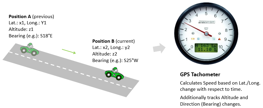
Now, given the ability of the system to measure the orientation, angular velocity, and linear velocity of the object or person with the device, and given the origin location is known from the GPS navigation, any new or changed position or destination location can be easily calculated by the processor. In addition to the accelerometer for measuring the linear velocity, some devices can additionally have a dedicated GPS Tachometer to measure the speed of the object as it changes the geographic coordinates with respect to time, as illustrated in the image below.
Thus, using all the above techniques, any change in the positioning of the device is contiguously updated and shown in the calibrated digital map with the geographic Lat./Long. coordinates coded. On top of that, maps like Google Maps show an additional layer of traffic congestion data collected from the users on the same map, thereby adding more value and richness to the navigation map.
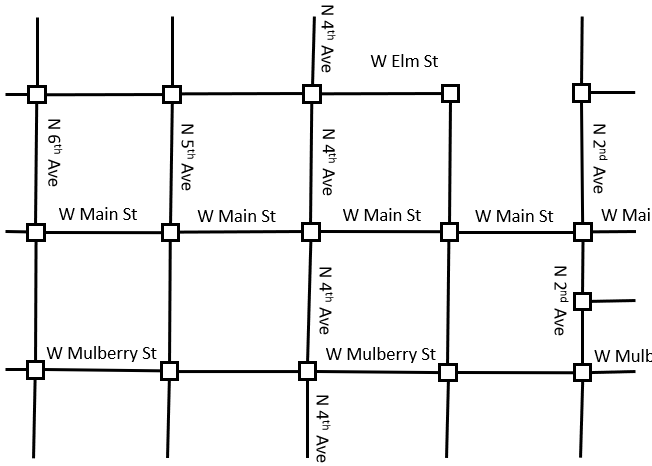
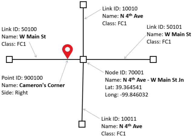
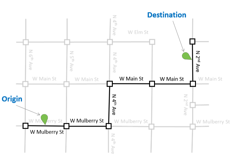
Now, quickly let’s see how the digital map used in the navigation system is constructed. As illustrated in the images below, a digital map may appear as a smooth image of the surface, but the roads and locations in the digital map are actually a network of Links (line segments), Nodes, and Points, and all points are coded with geographic Lat./Long. coordinates. So, as the navigation system locates the position of the device on the ground through the above methods, the system then plots that point on the already calibrated digital map. If a user selects a destination point to travel to, the system then tries to figure out the shortest route through the network of Links, Nodes, and Points, joining the current position as the Origin to the selected point as Destination, and then based on the database coding on these elements, the system picks the coded info to provide the turn-by-turn guidance as the device moves in this already determined path.

So, next time when you use a navigation system, please respect the collaborative efforts of the hidden tools, techniques, and geometrical and mathematical calculations, calibrated digital map designs, and the network guidance logics, etc., that continuously run in the backend to provide you the position or navigation on a nice colourful map on the screen! 🙂